Sunday, August 23, 2020

Just about finished...


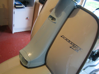
Well, it's the first day for a while that it hasn't been raining or sleeting. So I figured that as the scooter is so close to being done, I might as well get her out of the garage and take a few nice shots of her.
Next week, the plan is to do a good, overall check of the work to make sure I didn't forget anything, get her up and running and play around with the gear selectors to make sure she runs well and goes through the gears OK. I'll also check the brakes and everything is tight before giving this Lambretta a final clean and polish.

After that, the scooter will be winging its way back to Armandos in the back of their van and at that point, it will be given a full MOT Test and get its number plate from DVLA. so whoever is fortunate enough to buy this scooter will simply have to bring along a helmet.

Enjoy looking at her for now. More to follow next week.


And just to prove she is a genuine 1963 Italian stallion, here's the letter of authentication.


Fitting headset top & headlight

Here is our ultra rare Carello unit we described earlier.


And he original block for the wiring. This is inserted in to the rear of the headlamp unit bulb first.


And then clip it in place with the wire clip as shown.


On the underside of the headset top, you can see the previously installed, NOS speedomoter. There are two holes, one for the speedo bulb and the threaded one for the speedo cable.


The speedo is held in place with the retaining clamp and three screws with washers.


Insert the speedo bulb...


...now insert the speedo cable. You may need to remove the cable from the retainer on the foks in order to get enough cable space to have room to get your hand in there.


Here are the correct bolts and washers to join the two headset halves.


With the headset fastened together, push over the rim carefully, and fasten with the correct screws and washers. I use cup washers here for a nice, neat finish.


Now add the bolt to the underside of the headset through the slot for the beam adjustment. Use a flat washer.


Here is is completed.

Adding the horncasting and grille

We are getting down to the last few bits now.


Tap out all the threads in the grille and casting to ensure they are free of paint.


Fasten on the grille to the horncasting and then place the lower rubber on top of the mudguard. Offer the horcasting up to the scooter inserting the TOP edge first. The, push in the bottom ensuring is fits snugly on the lover rubber beading. With it in place but not secured with bolts, place the side strip rubbers in to position.

It can be a bit fiddly, and it is worth stopping and checking when tightening everything up, that none of the beading rubbers have moved. I fasten the top two fittings first, using to bolts with 8mm heads and washers. Make sure you use the correct10mm length bolts as loger ones will break the casting lugs if you tighten them too much to get the fit right.


Next, I fasten the badge plate and casting to the steering bracket on the frame using the correct allen headed bolts as shown.


Here it is done. You can see the mouth of the clip, in to which the badge sits.


Here is the lug on the rear of the badge that goes in to the clip.


And fitted!


Now you can continue to add the fastening bolts but keep checking to make sure you have nice, tight fitting beading.


Don't forget the two 8mm headed bolts and washers that go under the mudguard in to the horncasting.


And finally, the bolts with slotted, bevel heads and cup washers to finish off the inside of the legshields neatly.


Horncasting is completed.


Adding lights switch & headset wiring & horn wiring

Here is our quality replacement light switch.


Along with the two screws to attach it to the handlebars.


The wires behind the switch need to be fed through the apperture in the housing, if you cannot get them to go, you will need to slacken off teh brake, undo the housing bolts and remove the throttle roller in order to pull away the housing a little to get all the wires through. Do NOT pull on the wires.

With the wires through, fasten the switch to the housing using the bolts in the kit.


The switch wiring is fed as shown in to the headset.


And secured under the alloy clip.


The two wires for the horn brach off and go down as shown in the picture below.


Feed them down behind the legshield bracket.


And insert in to the horn connectors. It doesn't matter which way round they go.


Now connect all the wires from your switch to the headset block floowing the wiring diagram posted earlier. Notice the loom wires are already in from a previous post.


Install steering lock

The steering lock is definitely one of those jobs that is best done on the bench whilst the headset is off the scooter. Adding it now is a little more tricky, but because we didn't have the parts at the appropriate time, we have no choice but to do it now.

The lock fits in the hole to the right of the green wire you can see in the pic below.


Here is the actual plunger, spring, grub screw and cap to fit the lock.


Make sure the hole for the punger as shown above is clear of paint and that the plunger actually goes up and down in it smoothly. Grease the plunger and spring and offer them in to the hole.


The plunger should drop in to the hole and spring back up because of resistance on the spring.

Below, it is fitted and a glob of grease is added to the upper surface of the plunger.


The lock itself can only be inserted one way and the giveaway is this hole drilled in to the body of it. This indicated the barrel of the lock which goes uppermost.


Turn the key, so that the lock is OFF. This is indicated by the rounded part of the lock arm being uppermost and adjascent to the hole in the barrel.

 The shot above, shows the lock in "locked" position. Turn it off to insert the barrel in to the hole in the headset.

Push the key and lock barrel in to the headset whilst pushing down the plunger with a screwdriver until the barrel will go no further. You may need to turn the barrel one way or the other until the hole in the barrel can be seen through the threaded hole for the grubscrew which holds the barrel in place.


When they do line up, insert and tighten the grub screw.

This simply stops the barrel rotating when you turn the key.


Check the lock to ensure it works properly by turning the steering to one side or the other and putting the key to ON position. The steering should be locked. Now push in the alloy protective dust cap over the plunger. Job done.