Finally time to start putting this brake back together.
Here is a selection of parts I have bought to either replace missing parts or replace parts that were a bit past it. Can't be too careful with your brakes.
And here are a collection of parts I already had. I may mix and match them depending upon some of the parts under scrutiny or just preference. I need this brake to be reliable.
The brand new parts were supplied by Mark Broadhurst at MB Scooters. They are exceptional quality and they were very helpful with advice and tips for re-building this brake project and they are only a few miles from me, although you can order online.
First I put down an old towel under the brake and added the hub nuts and washers to protect the lugs as I tipped it over and over when working on it.
First job is to install the inner bearing. It goes down the centre tube as you can see below and comes to rest on the shoulder you can see inside.
I'm using CV grease, which is great for bearings and responds well to high temperatures.
Pack one side of the bearing with grease and place it grease side down over the tube. I drifted it down with a large socket which sat on the shoulder of the bearing but fitted inside the tube (just). This side might take a bit of persuading to go down but if you hit it carefully and centrally, it will go. You can tell when it is fully seated because there is a distinctive change in the sound as it is tapped home. I'll show the drift later.
Now pack the top of the bearing with grease.
Here are the bearings used for the inner cylinder. Two are required. They are both identical.
Next, flip over the hub and drop in the spacer tube. I've added a bit of grease to each end by pushing it in the grease pot a little bit at each end.
Now we can install the outer bearing. (I've taken out the spacer tube temporarily so you can see properly inside). Again, note the collar part way down the tube for the bearing to rest on.
Again, pack the bearing on one side and insert grease side down. You should also add a little grease to the neck of the tube.
Now, remembering to re-insert the spacer tube, I can drift down the bearing. This one usually goes in pretty easily but make sure you tap it down straight. Also, listen for the change in tone when tapping it as it seats itself on the shoulder.
Now you can clearly see my socket used to tap home the bearing.

Now fit the circlip, which fits in the small groove cut specifically for it. Make absolutely sure it is seated properly. And then pack the bearing upper face with more grease.

Now I can insert the seals. These are fitted with a spring inside which is visible from one side. I'm fitting them with the spring side facing the grease.
You should be able to push these in using just your fingers.
Now you can fit the smaller of the 2 top hats into the centre of the seal.
Now, on the actuator side of the hub, fit the larger seal into it's slot. This acts to protect the grease from the speedometer drive entering the brake disc system.
Below is a pic of the disc pads straight out of the box. Be aware, that brand new, they are unlikely to fit in place. The actual pads are fine, but the backing metal plate is generally too large to fit down the hole. You really need a bench grinder to take material off the edges all the way around the circumference to reduce them in size enough for them to drop into place.
The disc finally fits. This pad is static so if it is snug, it doesn't really matter just as long as it is definitely seated correctly.
Here you can see just how much material I had to remove from the edge of the pad backing plate to make it fit. Ensure that the top pad fits easily as this is the one which moves when the brakes are applied when using the scooter.
That's as far as I can go with this bit because the actuator I have on order has not arrived yet. So lets move on to the disc.
In the image below, you can see the disc with the anti rattle clip inserted in a slot which is in the inner ring of the disc. It is a sprung steel length of wire and is very tight in the disc. Getting it in is a bit tricky. My genius method is to insert one end and whilst holding it down with my fingers, use a clamp to squeeze it together and tap it down with a small hammer. However, while doing this, it snapped out of the clamp and went bang into the correct place. VERY lucky. I'm not taking more pics because it's even more boring trying to get it out.
ATTENTION:
I'm told that the disc will move easier along the studs (thus making the brake work more effectively) if this wire isn't fitted and it is perfectly safe to leave it off. However, if you decide to go this route, the disc WILL rattle at very slow speeds or when going on and off the stand. I'm having it ON.
Hard to explain this bit, but the actual disc only fits on the 3 studs when it is rotated to the correct position. The studs are NOT evenly spaced. First, get your disc and align it with the 3 studs on the main hub. Then, remove the disc and place the main hub down but remember the position of the studs.
Now, place the disc in the actuator side pocket of the hub body like this:
Now place the main half of the hub over it and align the studs with the disc holes and push both halves together.
Now you can install the main axle bolt this way around. Make absolutely sure the spacer tube is in the right position and if needed, use a little persuasion to drive the bolt through. It can often be quite tight.
Now pop on a couple of washers and the end nut.
Now flip over the hub and insert the larger top hat into the seal. Add your nut and tighten fully to bring the 2 halves together properly.
Almost there. This top hat will seat correctly when fully tightened.
Now I can fit the new MB metal speedo drive.
Dip the worm part in your grease and insert it into the hole provided. Turn the hub slowly as you do this and you will feel it drop into position. If you don't turn the hub and it isn't in right, it will strip the threads from the drive when in use. Never push this speedo worm in without rotating the wheel when doing routine maintenance or replacing this part.
Now you can insert the housing.
And tighten down.
To check it is working properly, I use a kitchen spike. It's wooden with a point at one end. I just cut the point off and it fits in the inner drive hole perfectly. But turning the hub in your hands, you should see the wooden stick rotate slowly. If it does, all is good. If not, the drive isn't located properly. Do NOT rotate the hub any further. Take it out immediately and re-install properly.
Now you can install your brake cable top hat stop and grease nipple.
Note: Some disc brakes have two grease nipples. Mine only has one, it's between the two bearings. The one over the speedo housing is blanked off on this hub.
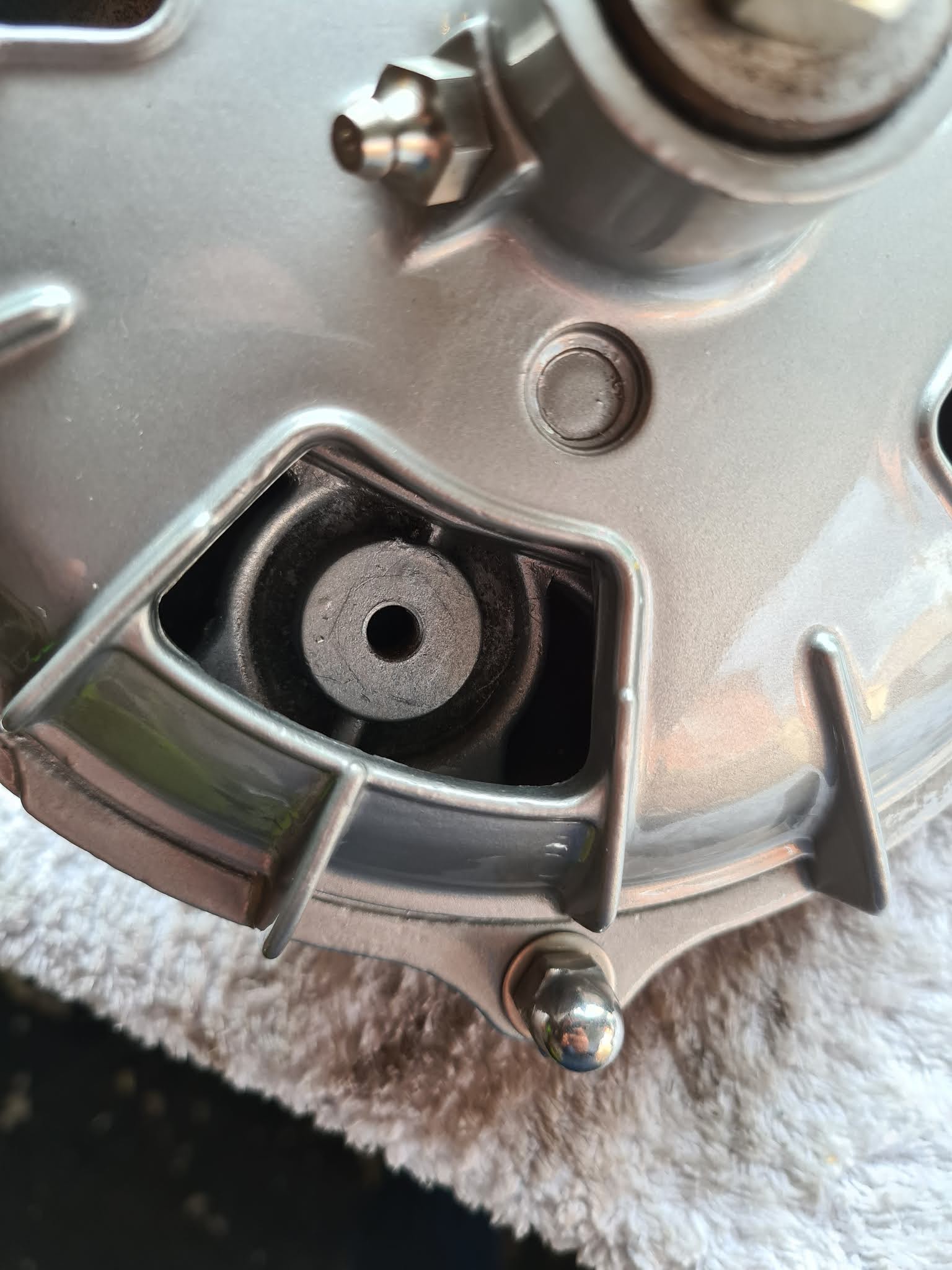
Now you should rotate your hub so that in one of the windows you can see the lock position.
Insert the threaded stud through the tab seen above and using an allen key, screw the stud down until you feel resistance against the disc. When you do, undo the stud by half a turn.
Once in position, place the locking nut over the stud and tighten it down, whilst holding the stud in place with your allen key.
Now, you can install the brake disc plastic windows. The way I do it, is to insert the outer edge first...

Then, using both thumbs, push hard forward and down until it pops into place.
Try not to bend, heat or cut them to fit. They break VERY easily and original ones are extremely hard to find nowadays.
So now, these are the only bits I have left. The floating pad, circlip for the actuator and the Innocenti 'i' cap. Clearly, this is as far as I can go for now until the actuator arrives from Rimini.
When it does, we can finish off this little job. I'll update when it arrives.