Remove the horn.
It is fastened to the frame steering column upper using a single bolt on to a captive bolt. Under the nut is a flat washer and then a "U" bracket. Then, you can remove the horn from its bracket by undoing the two Allen head bolts which attach to captive nuts either side. You can keep the bracket but unless you are retaining the original 6 volt system, you can discard the horn. Part of the upgrade for modern use, means a new 12 volt electrical system will be installed.

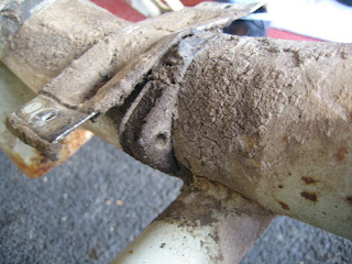
Here is where the horn was located. Keep this thread clean and free from damage.

Remove the choke.
Here, behind teh choke fitting, you can see it is attached to the frame via a single nut.

Pull back the choke cover to reveal the spindle in to which the inner choke cable is located. Remove the inner choke cable for the split spindle and the choke cable can be removed also.

Here we see the components in order. The nut used to affix the setup, with a star washer, followed by the wire retaining clip, used to hold your cables in position and prevent chafing when the scooter is in use. I will illustrate how this all goes back together correctly when we re-assemble the machine.

The choke housing can only enter the frame one way due to a groove in the choke having to correspond with a notch on the aperture.

Remove any final cable ties (noting their position). This one, just behind the engine mount tube, has a rubber fitting underneath it. This rubber has a hole drilled through in to which your HT lead passes to help keep it out of the way of moving components when the scooter is in use.
Pull out the cones from the frame tube where the engine mounting bolt passes.

Remove the "dog leg", rear footboard support from the kickstart side only, by undoing the two nuts and bolts.

Here is is off the frame. The dog leg on the flywheel side is welded in place and does not come off.


Remove the coil (CDI Unit).
The coil is held in a clamp that attaches to the frame via two long bolts that pass through the frame. Undo both and remove the coil and bracket complete and then remove the coil from the clamp.


Remove the rear mudguard.
There are two nuts and bolts toward the front of the scooter and a single one in the centre toward the rear.


With all three undone, you can lift out the mudguard.

Remove the side panel clips and brackets.
The rollers on the inside of your side panel handles fit on to this wire clip. It is held in place by two brackets attached to the rear of the scooter and normally hidden by the number plate.
On the outside of the scooter, you should see 4 flat countersunk heads of the 4 bolts used. On the inside of the frame (see below), you see the 4 nuts you need to remove and the correct positioning of the brackets used to hold the clip in position.
At the top of the clip, you should notice a lug welded to the rear of the frame that hols the clip in an upright position.

Remove the stand.
The stand is held in place by the brackets attached to the splash plate. Through this bracket pass two nuts and bolts, which enter the frame struts and lock the whole assembly in place. You can access the bolt via a specifically designed hole to the rear of the strut on to which you can put your socket wrench. Use a spanner on the inside of the frame strut aperture to hold it in place whilst undoing the two with the socket. When you have removed both nuts and bolts, the stand and splash plate assembly can be taken away from the frame after releasing the stand spring from it lugs.
Your frame is now stripped.

It is fastened to the frame steering column upper using a single bolt on to a captive bolt. Under the nut is a flat washer and then a "U" bracket. Then, you can remove the horn from its bracket by undoing the two Allen head bolts which attach to captive nuts either side. You can keep the bracket but unless you are retaining the original 6 volt system, you can discard the horn. Part of the upgrade for modern use, means a new 12 volt electrical system will be installed.

Here is where the horn was located. Keep this thread clean and free from damage.

Remove the choke.
Here, behind teh choke fitting, you can see it is attached to the frame via a single nut.

Pull back the choke cover to reveal the spindle in to which the inner choke cable is located. Remove the inner choke cable for the split spindle and the choke cable can be removed also.

Here we see the components in order. The nut used to affix the setup, with a star washer, followed by the wire retaining clip, used to hold your cables in position and prevent chafing when the scooter is in use. I will illustrate how this all goes back together correctly when we re-assemble the machine.

The choke housing can only enter the frame one way due to a groove in the choke having to correspond with a notch on the aperture.

Remove any final cable ties (noting their position). This one, just behind the engine mount tube, has a rubber fitting underneath it. This rubber has a hole drilled through in to which your HT lead passes to help keep it out of the way of moving components when the scooter is in use.

Pull out the cones from the frame tube where the engine mounting bolt passes.

Remove the "dog leg", rear footboard support from the kickstart side only, by undoing the two nuts and bolts.

Here is is off the frame. The dog leg on the flywheel side is welded in place and does not come off.


Remove the coil (CDI Unit).
The coil is held in a clamp that attaches to the frame via two long bolts that pass through the frame. Undo both and remove the coil and bracket complete and then remove the coil from the clamp.


Remove the rear mudguard.
There are two nuts and bolts toward the front of the scooter and a single one in the centre toward the rear.


With all three undone, you can lift out the mudguard.

Remove the side panel clips and brackets.
The rollers on the inside of your side panel handles fit on to this wire clip. It is held in place by two brackets attached to the rear of the scooter and normally hidden by the number plate.
On the outside of the scooter, you should see 4 flat countersunk heads of the 4 bolts used. On the inside of the frame (see below), you see the 4 nuts you need to remove and the correct positioning of the brackets used to hold the clip in position.
At the top of the clip, you should notice a lug welded to the rear of the frame that hols the clip in an upright position.

Remove the stand.
The stand is held in place by the brackets attached to the splash plate. Through this bracket pass two nuts and bolts, which enter the frame struts and lock the whole assembly in place. You can access the bolt via a specifically designed hole to the rear of the strut on to which you can put your socket wrench. Use a spanner on the inside of the frame strut aperture to hold it in place whilst undoing the two with the socket. When you have removed both nuts and bolts, the stand and splash plate assembly can be taken away from the frame after releasing the stand spring from it lugs.
Your frame is now stripped.
