It is possible to remove these one part at a time, but, as you will be removing nuts and bolts that hold various parts together at the same time, we can do this all in one procedure.
Firstly, remove the
caps holding on the rubber legshield trim. Below you can see the top
one on the left hand side, which consists of two parts surrounding the
trim to hold it in place. The part toward the rider has a slightly
larger hole for a bolt to pass through, the part toward the mudguard is
threaded. So the bolt that fastens the two together has the head facing
the rider.
This setup is
the same at both sides of the top of the legshields, either side of the
rear of the horncasting. Follow the rubber trim down and remove both
trim clips from the bottom side too. Then simply peel away the rubber
trim.
Most
of the outer trim on this scooter is missing, presumably damaged. But a
few of the bolts that used to hold it in place still remain. These need
to be removed. Most of these were way too rusty to be undone with a
spanner and had to be carefully ground off. If your outer edge trim is
still there, you will need to remove all the nuts from under the scooter
that hold this trim in place as well as the "spring clips" that are
pressed on to the small lugs that go through the holes in the
legshields. The spring clips are pressed on to these lugs with NO
anti-vibration rubbers underneath. Although it is common for restorers
to use them nowadays, they were not fitted at the factory.
Remove ALL the trim end caps, then remove the rubber strips from within the alloy channel, and then remove all the bolts passing through them to affix the channels to the frame struts. You will notice that the end cap in the outer position is attached using a barrel nut for neatness, as this fitting can be seen on the front of the legshields and it is much smarter than being able to see a bare nut and bolt fastening.
Other fasteners are tucked away inside the front mudguard. All of them need to be removed. Here, you can see the left hand side is almost done.
And here, the right hand side are also removed.
Remove the two bolts securing the top of the legshields to the top of the horncasting.
If you were lucky enough to still have a horncast badge, this is where it would be fitted. Mine is missing, but you can remove yours by inserting a sharp screwdriver and gently prying it off. You can see that behind it, is a spring clip that a lug on the back of the badge presses in to.
The two bolts either side are dual purpose. They hold the clip to the horncasting as well as the horncasting to the frame. Remove both these using an Allen key.
Like so:
Once these two Allen bolts are removed, the horncasting and mudguard can be removed whilst still attached to each other.
Remove the horncasting grille from the horncasting be undoing the following bolts.
IMPORTANT: For an anorak restoration, it is not necessary to remove the grille at all. They were usually attached in the factory when painted, bolt heads and all.
Remove the horncasting from the mudguard by undoing the final two bolts indicated below.
The horncasting, when fitted to the mudguard and legshields is seated on the following trim pieces. From left to right, the gasket that goes under the horncasting, in-between the mudguard top. Two thin strips down each side of the horncasting and the final two gaskets for either side of the mudguard. All of this trim makes for a nice, smart appearance and tidy lines as well as preventing rattles and vibration. It also helps to channel away water.
Behind the horncast, we see the Innocenti Logo along with the part number: 19.95.0086
Behind the grille, are the cast markings:
19.95.0083
FPB A - 1886 2
Behind the horncast, we can now see the final legshield bracket fixing the legshields to the frame. These are two bolts passing through a captive nut on the legshield bracket. Remove both.

By carefully flexing back the legshields, you can open this bracket wide enough for it to slip over the frame tube and pull back toward the rear of the scooter. You can now lift away the legshields completely.
Behind the frame tube is a rubber strip which acts as an anti vibration buffer. Here it is shown being removed.
I have labeled the wiring cables to take photographs and make notes of the order. This is VERY important. The wires and loom MUST be positioned properly on the frame AND in the correct order. Routing them right is a must. If you get this wrong, at best your cables will be ineffective and operate poorly. At worst, they will snag or wear and could be potentially dangerous.
See that on the left of the scooter, the wiring harness is to the front, followed by the cable for 1st gear, then 2, 3, 4th gear and lastly, the front brake.
The position of the single alloy clip holding them in position.
On the right of the scooter, the throttle cable is toward the rear, then the clutch cable, then at the front, the two sleeved wires for the horn.
At the lower, front end of the frame tube, is the grease junction, which holds 4 cables. It is important you get yours in the correct order. Innocenti scooters used this block on all models this age and the order of the cables entering and leaving this block was standard. In other words, if your scooter has a grease junction like this, they will ALWAYS be in the same order.
From top to bottom:
1. Throttle
2. Clutch
3. First Gear
4. 2nd, 3rd, 4th Gear
The two gear cables wrap under the front of the frame after the fixing strap. The Front brake cable is routed differently and will be explained during the re-build.
You can see another strap just behind the brake pivot after which, the throttle cable goes over the frame tube and over the top of the wiring loom to it's final position at the carb. You might also notice a strap just after the bracket for the rear brake cable, almost as we get to the front of the canopy. Under this strap is a triangular rubber spacer which has a hole for the throttle cable to pass through to prevent it squashing on the loom.
You can see that better in the picture from this side. See that this strap does NOT hold down the loom. Also take note of the wire branching off from the loom traveling toward the rear brake switch.
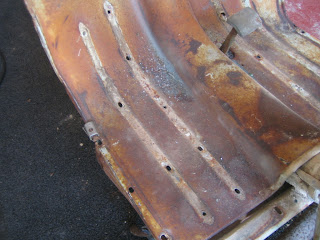
Lastly, on the pictures of the frame struts, you can clearly see marks left by the round, rubber washers used as anti-vibration buffers between the struts and the legshields. They were sandwiched there when the legshields were initially attached. (You can see one on the floor in the image above). Under the very last holes on the outer edge of each strut, the rubber buffers used were rectangular.
To free the loom, we need to remove the Regulator attached to the frame.
It is attached via bolt situated at the rear of the box. Notice it has been used as an earthing point. Don't worry about wiring too much at this point, as the colours and type of system will be uprated to something more suitable for modern performance.
With the regulator off, you can detach all the bullet connectors and strip out the wiring loom completely.


