Shown below is the genuine cover for the CDI unit. Passed through it are
the green, white and red wires from the stator plate and a green wire
from the loom. The yellow wire you can see branches off toward the
rectifier.
Attach the four wires to the CDI.

And fit the rubber cover as shown.

This is yet another genuine cover for the regulator. However, it was quite hard due to age and very tight to fit. For the purpose of this work today, I have shown the wiring without it, but it WILL be fitted when the wiring is completed.

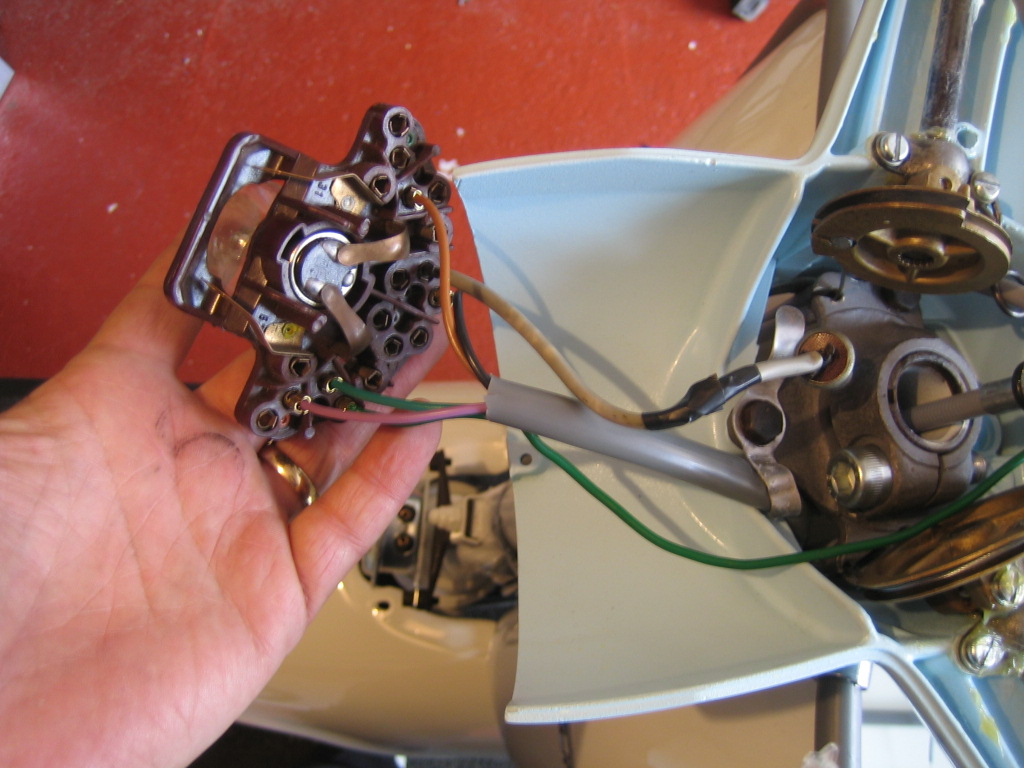
Here we see the yellow wire fitted to the regulator where the yellow dot is. The pink, purple and brown wires from the loom are all joined together and go to the dot marked in grey. The last dot on the regulator is black and indicates earth. Here, you can see the earth braid.

The earth braid travels down and is attached to the legshield strut with a nut and bolt via an inline ring fastener and then down to the top of the flywheel cover, where it is attached at the same point the flywheel cover is fixed uppermost.

The headset wiring block is divided in to sections of individual, dual and triple connections. By turning your wiring block over, you can see which ones are linked.
Using the wiring diagram posted earlier in the build, connect the wires as required. Some wires, like the black ones for example need to be connected in a block that allows 3 to be joined, as long as you allow for this, you can put the wires anywhere as long as they connect together as shown.
Here is the wiring diagram posted previously for reference. Print it out if that helps:

No comments:
Post a Comment
Please keep it friendly.