Sunday, August 23, 2020

Don't forget engine oil

Easy to forget, but probably fatal for your engine if you do it.

Remove the upper oil filler plug.


Make sure you do not loose the filler plug fibre washer.


Use a funnel in the engine filler hole.


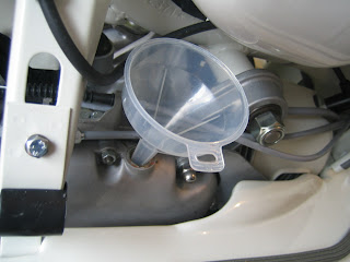
and add 750ml (three quarters of a litre) to a dry engine.


Remember, we are adding this to a totally dry engine, so after initial running checks and setup, we will be checking the levels again using the level plug as some oil will be lost when circulating the engine and soaking the clutch etc.

Normally, you will drain the oil using the lower of the two plugs in the bottom of the engine and check the level by filling from the top until it starts to seep from the upper two plugs (the level plug).


The engine is ready to roll.


Adding fasteners and supressor cap to HT lead


The HT lead already comes from the CDI Unit as was attached in a previous post.

Next job is to secure it to the frame en-route to the sparking plug.

You will need a rubber grommit like this.


Slip the grommet over the plug end of the HT lead


Push the grommet right up the lead and then pass the lead down through the tab on the legshield support like so...


Now, the grommet and lead leed to be secured by the metal tab. If yours will not pass under it, you will need to open up the tab VERY gently. The tab can break off pretty easily.


It should look like this.


Whatever model you are working on or whatever CDI, Coil, Regulator setup, your HT Lead should go over the rear shock absorber support like this.


Pass a rubber bridge over the HT Lead end.


Attach to the frame using the last of your frame alloy clips as previously shown. It goes just in front of the bracket for the airbox.


This is my favorit kind of supressor cap as they very rarely come off. Insert the HT Lead in to the cap shaft and push home as far as possible.


Look in to the cap and you will see it is all the way home.


Now screw in the plug clip. This not only grips the head of the sparking plug, it also pierces and secured the HT Lead.


Like this.


You can remove the alloy cap from the top of the sparking plug and pop on the cap.

Installing the kick start pedal

If you have to buy a new one, make absolutely sure it is the correct one for your scooter. There are many different kinds and the wrong one will mean a bad fit, incorrect depth and loss of kick travel or even worse, damage the spline on your kickstart shaft.


Fit the pedal rubber.


Push the kickstart pedal on to the engine shaft making sure the tab is as close to being in line with the stopper rubber inserted in the engine. Don't worry if the best spline to fit the pedal means the stopper is very slightly over or under, but more than a few mm is not good.


Affix the bolt from above like so...


And tighten using a split washer on the underside. You don't want this bolt getting loose whilst in use or the pedal WILL go missing.

Rear footbrake install and setup

Installing the footbrake normally required the footbrake pedal, cable adjuster link, two washers and a circlip.


Offer the pedal up to the floorboard at and angle thus...


...if it is tight in the hole, removing the pedal rubber can help, but once through it can be left to sit like this for now.


Put plenty of of copper grease on the footbrake stub.


Insert the rear brake return spring in to the hole in the frame. The lever part of the spring will be pointing upward.


Now put on the rear, lerger of the two washers.


Next, slip the pedal on to the stub and push home as far as possible.


Use a spring puller or cable tie in a loop to pull down the return spring leg until it is under the brake pedal.


Normally, the brake pedal can now be pushed right on to the stub, but if your spring is brand new, they can be very tight and prevent the pedal from seating all the way back. If this is the case, it may be necessary to compress the spring, which in effect, opens the centre hole and allows you to push the pedal right on to the stub until it is protruding out from the front edge.

I use stilsons to compress the spring upward and at the same time, tap the pedal home with a small hammer.


Now you can add the second, thin washer and your circlip. don't worry if there is no room for the second washer, sometimes it won't fit, so the circlip is added flush against the copper bush in the pedal hole.


Make certain the circlip is snug in the groove on the stub and that the pedasl stop is touching the frame. Also note that the switch is depressed by the block on the pedal. The switch is actuated by being released, rather than depressed.


Check that the adjuster, previously added in another post, is actually wound off as much as possible.


Insert the inner cable through the hole in the adjuster trunnion, pull on it with pliers and tighten the 14mm nut to secure it.


Only a minor adjustment should be required at the rear adjuster to ensure the brake activates correctly and the rear wheel spins when released.

Badges and stickers

A few finishing touches to the days work for today.


Here is an original petrol flap sticker, which is actually a very thin sheet of aluminium foil. These were factory fitted items and it would have been sold in the UK with a sticker like this. So ours is having one.

Lift the petrol flap.


And if you buy a remade sticker, make certain that you peel the backing OFF the sticker and not the other way around. If you try to peel the sticker off, it will curl or crease.

No great amount of care was taken when the original stickers were fitted and you often see them at all kinds of strange angles. Just for the sake of it, I've put ours on as straight as possible.


For adding the legshield badges, please see the post on the sidepanels. Fitting these badges is carried out in exactly the same way.

Starting to look like a proper Lambretta now.

Installing cut out button (kill switch)

Very simple job.


Notice the kill switch has a bracket attached to the rear, inner section of the housing. It is held in place with a small grub screw, which passes through the bracket and in to the rear body of the switch. Remove the screw, being careful not to lose the small flat washer underneath.


The kill switch has a slotted upper section in the housing, this is designed so that the peg sticking down from the hole in the headset can fit into it. So the switch can only go in one way around and the peg will help to prevent it from swivelling around during use.


Push the green earth wire through the hole in the headset and then the switch itself.


Whilst holding the switch in place, insert the bracket over the inside as shown so that it is level with the ground. See picture below.

Tighten the grub screw but don't overdo it.