Sunday, August 23, 2020

Adding seat

Here is our seat base back from being stripped of all the original paint and rust etc. It has been painted black, exactly as it should be. Alongside it are the rubber frame buffer and rear catch.


Original marking for "Giuliari" accross the centre cross member.


Don't forget to put back a new rubber buffer on the end of the seat catch push rod.


Here is our new seat cover as original spec.


Note the alloy tabs on the inside, which you will have to turn upright after the seat cover has been put on the base.


Insert the base in to the cover starting at the rear end first and then push in the front. It might be a bit of a stretch but with effort, it will go.

Then, start bending the cover tabs over the frame loop by first (with the seat upside down) pushing the top tab down and then the lower tab up and over it.

This prevents the alloy tabs from scratching or catching on your painted frame when the scooter is in use as it keeps the sharp edges away from the panelwork.


 With both tabs bent over, squash them flat using a hand clamp.


Work your way forward, both sides at the same time...


Until all the tabs are done.


 Your seat should now look like this.


Now, from the inside, push a sharp screwdriver or similar through the threaded hole where indicated to make a guide for the hole in the seat where the strap will be fitted. When you have done both sides, drill out the hole in the seat cover to 5mm.


You can now add the stap by insertign the strap end bolts through the cover and in to the threaded hole in the frame. It should then look like this:


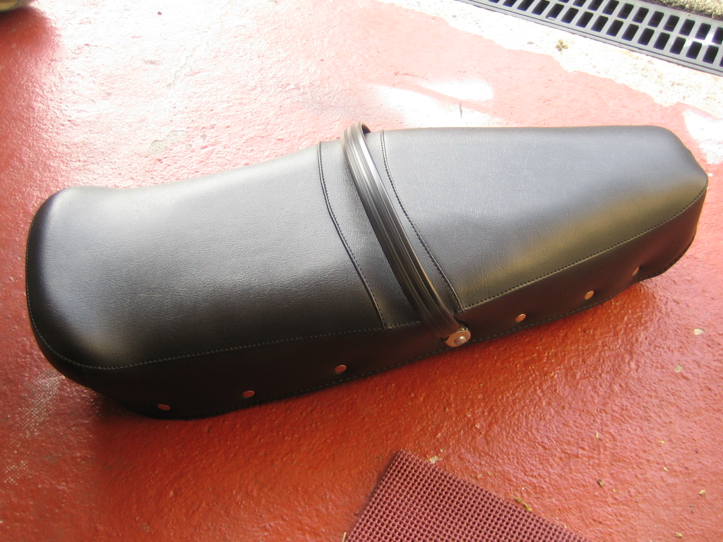
And be dead centre in the seat pattern as shown below.


Now insert the rubber buffer block.


You might need to drop it in boiling water and use a bit of soap to get it to go in to the frame holes. It is VERY tight!


Here is the fixing kit for the seat. 13mm bolts and nuts, plus washers. Notice, the rear bracket for the catch has nylon washers.


Fit the front hinge by adding a thicker washer (shown below) under the hinge and a slimmer one under the nut, which goes inside the toolbox.


Put the thicker washers in place under the air scoop.


Offer up the hinge and push two of the bolts through. This is easily a two man job.

Fasten these two bolts loosely with a washer and nut on the underside of the frame in the toolbox. Then, slip in the front two thick washers and insert the front bolts and fasten. Don't fasten them all too tightly as we may need to adjust the position of the seat a little when fitting the rear catch.


It was at this point I realised we had picked up the wrong rear catch bracket. So for now, I'm using a sheet of bubble wrap to protect the frame and paint whilst the seat is down.


But it does look rather good with the seat added.


Here is the offending rear bracket. Notice the catch part is central on the bracket. Ours needs to be the type which is very similar, except with the catch to the left a little more. Oh well. I could always have the guys collect the scooter and add this themselves, it's such an easy job now to complete.

We ALL make mistakes.


The wiring loom

Shown below is the genuine cover for the CDI unit. Passed through it are the green, white and red wires from the stator plate and a green wire from the loom. The yellow wire you can see branches off toward the rectifier.

Attach the four wires to the CDI.


And fit the rubber cover as shown.


This is yet another genuine cover for the regulator. However, it was quite hard due to age and very tight to fit. For the purpose of this work today, I have shown the wiring without it, but it WILL be fitted when the wiring is completed.


Here we see the yellow wire fitted to the regulator where the yellow dot is. The pink, purple and brown wires from the loom are all joined together and go to the dot marked in grey. The last dot on the regulator is black and indicates earth. Here, you can see the earth braid.


The earth braid travels down and is attached to the legshield strut with a nut and bolt via an inline ring fastener and then down to the top of the flywheel cover, where it is attached at the same point the flywheel cover is fixed uppermost.


The headset wiring block is divided in to sections of individual, dual and triple connections. By turning your wiring block over, you can see which ones are linked.

Using the wiring diagram posted earlier in the build, connect the wires as required. Some wires, like the black ones for example need to be connected in a block that allows 3 to be joined, as long as you allow for this, you can put the wires anywhere as long as they connect together as shown.


Here is the wiring diagram posted previously for reference. Print it out if that helps:


One New Old Stock Carello Headlight

 For those in the know, this is probably the Holy Grail of headlights for the Li series Lambretta. A genuine, NOS Carello headlight unit complete with factory wiring block.  For those who don't, just know that this scooter has been fitted with the very best equipment. If you are the lucky new owner, nobody is going to be telling you this part or that part is wrong.


Notice that the block is held in place with a wire clip, I will be removing the block to make life a little easier wiring in the loom and switch etc. clipping it back in to the headlight unit is a very simple job.


Adding factory water slides

At the time of manufacture, all Li models imported to the UK would have been fitted with 3 waterslides. One with running in instructions on the inside legshiels, one with air filter cleaning instructions on the air filter elbow and a final one on the right hand side of the tool box for battery care.


It was a legal requirement that all scooters used in the UK had a parking light at this time and therefor, all models exported to the UK had a battery tray and battery as standard equipment.

As this model was made for the Italian market, no battery tray was fitted and thus, we only require two of the water slides.

Here is the 'running-in' water slide. First, remove the opaque cover from the front of it.


Then soak in water for around 30 seconds.


Turn it over carefully and soak for a further 30 seconds on the other side.


VERY carefully, push the slide upward and off the backing sheet and lay this exposed edge on to the scooter in the position shown.

Then, slowly slide the backing from the transfer as opposed to the other way around. Gently hold the transfer in place, whilst pulling the backing from underneath.


With a very soft clean cloth, carefully dab any excess water from the slide and press out any air bubbles. Minor wrinkles can be left as these will dry out and vanish by thenselves.


I personally think this is a nice addition to a factory restoration and really looks the part.


Soak the air filter slide as previous.


And apply where shown.

Installing the speedometer

 Standard speedos like this are getting increasingly hard to find these days. This one, I know is working 100% although the housing and face are yellowing slightly I am going to use it. It is totally original and quite rare.


These are the markings you look for when hunting for a genuine Innocenti Speedometer.


Insert the speedo into the headset top. It should be quite a snug fit. Make sure your headset top is on a nice soft surface with nothing to scratch it underneath.


Place on the retaining ring as shown.


and fasten down with three 5mm long screws which have round slotted heads.